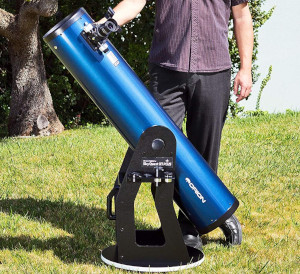
Orion Skyquest Xt8 Plus User Manual
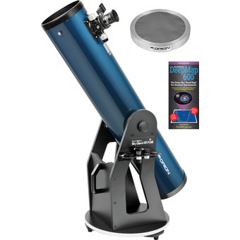
Posted : admin On 27.05.2020The SkyQuest XT8 PLUS telescope includes the popular DeepMap 600 folding star chart. This 'road map' of the cosmos will tell you just where to look in the night sky to find interesting objects to explore in the big XT8 PLUS Dobsonian Telescope.
- Orion SKYQUEST XT10 CLASSIC, SKYQUEST XT8 CLASSIC User Manual. Size: 916.02 Kb. Instruction Manual. Orion ® SkyQuest. XT6Classic, XT8 Classic. Traditional Dobsonian designs expect the user to compensate for heavier accessories by adding weight to the opposite end of the telescope tube. Such counterweighting systems can be.
- The Orion SkyQuest XT8 PLUS Dobsonian's sleek redesigned base not only has an appealing look, it also features cutouts for reducing weight to give the XT8 PLUS more portability than the previous XT8 classic model. The base has white trim to.
- It's easy to aim the XT8 PLUS easily and accurately with the included Orion EZ Finder II reflex sight. Also included are a quick collimation cap, and dust caps for the reflector telescope tube and focuser. For easy transport and storage, the Orion XT8 PLUS telescope can conveniently be broken-down into two separate pieces.
5
hole, and the large hole lines up with the central hole in
the baseplate. Thread an encoder board mounting screw
Have your camera's Serial Number ready before you begin.Download Instructions. For download instructions follow the steps below. These functions include downloading and displaying images, remote shooting, and camera control for each setting. EOS Utility is an application that brings together functions to communicate with the camera. Canon t2i service manual download. Select your model on the left side of this page.
into the predrilled starter hole with a Phillips screwdriver
and tighten until just tight.
6. Place one fender washer (H) onto the azimuth axis screw
(I). Then push the screw up through the hole in the ground
baseplate (A).Then slide the encoder disk (J), flat side
down, onto the azimuth axis screw.
7. Place the brass bushing (F) onto the azimuth axis screw

(I) so that the wide end of the bushing is closest to the
encoder disk (J). Seat the bushing onto the encoder disk
Refer to applicable Warranty & Maintenance Guide for details.For Toyota hybrid vehicles beginning with model year 2020, the hybrid (HV) battery is covered for 10 years from original date of first use or 150,000 miles, whichever comes first. The HV battery may have longer coverage under emissions warranty. On top of our basic coverage, we offer:Hybrid-Related Component Coverage Hybrid-related components, including the HV battery, battery control module, hybrid control module and inverter with converter, are covered for 8 years/100,000 miles. Refer to applicable Warranty & Maintenance Guide for details.Powertrain Coverage 60 months/60,000 miles (engine, transmission/transaxle, front-wheel-drive system, rear-wheel drive, seatbelts and airbags).Rust-Through Coverage 60 months/unlimited miles (corrosion perforation of sheet metal).Emissions Coverage Coverages vary under Federal and California regulations.
so that the registration feature on the bushing goes into
the hole in the encoder disk. You may need to move the
encoder disk around on the azimuth axis screw a bit in
order for the bushing to seat properly.

8. Carefully position the top baseplate (D) over the ground
baseplate (A) and lower it so the brass bushing (F) goes
into in the center hole of the top baseplate. Place the
remaining fender washer (K) onto the shaft of the azimuth
axis screw, then thread the hex lock nut (L) onto the end of
the azimuth axis screw and tighten it finger tight, for now.
9. To tighten the azimuth axis screw (I) and hex lock nut
(L), tilt the assembled Dobsonian base at a slight angle
to lift the ground baseplate off the ground. Now, with one
wrench (or pliers) hold the head of the azimuth axis screw
still while turning the hex lock nut with the other wrench.
Figure 4 shows this being done. Tighten the hex lock nut
just until the top fender washer is no longer moving freely,
then tighten the hex nut a 3/16-1/4 turn beyond that. This
ensures proper spacing between the encoder disk and the
azimuth encoder board.
10. Attach the handle (M) to the front brace (B) with the two
handle mounting hex-head screws. Place one washer on
each screw, then press the handle against the front brace
(the end of the handle with the logo should be up). Then
thread the screws from the inside of the base into the han-
dle until tight using the supplied crescent wrench.
Orion Skyquest Xt8 Manual
11. Line up one of the altitude bearing cylinders with the inside
of one of the four bearing cylinder holes on the side pan-
els. Push a bearing cylinder screw through the side panel
and bearing cylinder. Then thread it into the built-in hex nut
on the cylinder with the included hex key (Figure 5). The
beveled end of the cylinder should be facing away from
the side panel. Repeat this for the remaining three bearing
cylinders.
12. Attach the encoder connector board to the side panel. Place
the board against the side panel so that the modular jack fits
into the square-shaped hole and thread four encoder board
mounting screws through the connector board and into the
predrilled holes in the side panel until tight (Figure 6).
There are some predrilled holes on the side panel opposite
the panel that holds the encoder connector board. These
holes will be used to mount parts that come with the option-
al IntelliScope controller. If you purchased the IntelliScope
controller with your SkyQuest, you will want to follow the
installation instructions in the controller’s manual at this time.
installing the Vertical stop
Place the three flat washers onto the shaft of the vertical stop
screw. Thread the vertical stop into the threaded insert on the
inside of the front panel until tight (Figure 7). The position of
the vertical stop is adjustable by adding or removing wash-
ers. This is important when using the optional IntelliScope
Computerized Object Locator, since the optical tube must be
exactly vertical during the two-star alignment procedure.
Orion 8974 Skyquest Xt8 Plus
Figure 5.
Attaching the bearing cylinders. (XT10 Shown)
Figure 4.
To connect the baseplates, tilt them only slightly, as shown.
Do not place them on their side.
(a) Use one wrench to hold the hex nut
steady
(b) while turning the other end of the azimuth axis screw.
b.
a.
Correct Tension pads
Bearing
cylinders